DESCRIPTION
The IQ/QAM Transmitter is a high performance modulation evaluation unit that allows user to produce optical signals with complex modulation schemes (QPSK, QAM, OFDM). It integrates high bandwidth dual parallel Mach-Zehnder modulator and high speed RF drivers capable of dealing with data rate up to 56 Gbps. It features an embedded bias controller that allows to automatically set the modulator operating point.
FEATURE
C or L band wavelength range
Data-rate up to 56 Gbps
Automatic bias point setup and tracking
APPLICATION
Long Haul Optical Transmission
Microwave Photonics
Carrier-Suppressed Single Sideband
Testing and Measurement
SPECIFICATION
| Parameter | Unit | Min. | Typ. | Max. |
| Operating Wavelength | nm | 1530 | 1550 | 1610 |
| Optical Bandwidth | GHz | 22 | 25 | 28 |
| On/Off Extinction Ratio | dB | 20 | 26 | 32 |
| Insertion Loss | dB | 4.5 | 6.0 | 7.5 |
| Maximum Data Rate | Gbps | 40 | 50 | 56 |
| Chirp, Alpha Parameter | dB | -0.1 | 0 | +0.1 |
| Input Optical Power @ CW | dBm | -15 | 10 | 15 |
| RF-MZI Electrode | – | Internal Push-Pull Drive Voltage Vpi Typ. 3.5V@22Gbps |
||
| RF Input Amplitude @50Ω | mVpp | 100 | 500 | 1000 |
| RF Channel Gain Difference | dB | – | 0.5 | – |
| RF Gain Adjustment Range | dB | 0 | 10 | 21 |
| Eye Diagram Adjustment | – | Jitter and Cross-over | ||
| Bias Control Mode | – | Automatic | ||
| Modulation Format Application |
– | IQ/QPSK/QAM/CS-SSC | ||
| Optical Input Option | – | Tunable Laser | ||
| RF Input Port | – | SMA Female (2.92mm Compatibal) | 50Ohms | 2 Ports |
| Optical Fiber and Connector | – | PM1550, FC/APC | ||
| Adjustment Interface | – | Manual Trimming Potentiometer |
||
| Operating Temperature | ℃ | 0 ~50 | ||
| Power supply* | – | DC 12V, 1A (EVB) | ||
| Dimensions (L×W×H)* | mm | 200×150×32 (EVB) |
Notes:*The specifications subject to change without notice.
*The appearance and the key component vary according to different performance requirements.
ORDER INFORMATION
TX-IQ-1-2-3-4-5-6
| 1 | 2 | 3 | 4 | 5 | 6 |
| Data Ratio | Package | Wavelength | Optional 1 | Optional 2 | Connector |
| 10=10Gbps | B=Board | C=C band | BC=Bias | DR=RF Driver | FA=FC/APC |
| 40=40Gbps | M=Module | L=L band | N=No BC | N=No DR | NA=None |
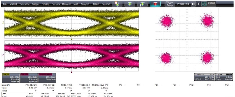
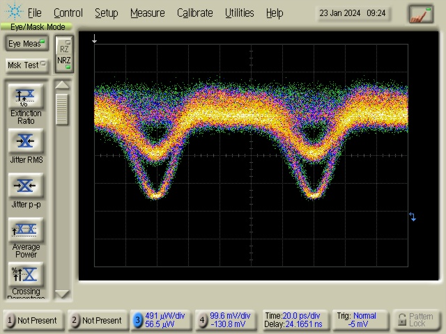
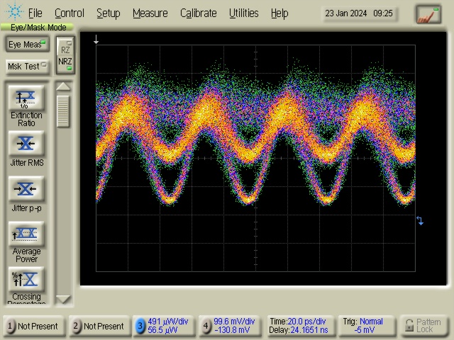
EYE DIAGRAM Symbol Rate at 10GBaud & Symbol Rate at 20GBaud
CONSTELLATION PERFORMANCE Symbol Rate at 20GBaud