DESCRIPTION
The EDFA adopts unique design to produce maximum signal gain and saturated output power while maintaining low noise figure, enabling test capabilities in system or component level manufacturing and characterization, as well as facilitating highly demanding R&D applications.
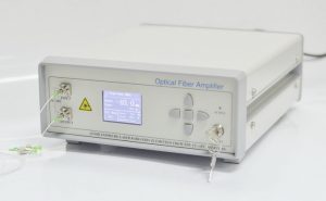
The turnkey bench-top unit incorporates an user-friendly front panel housing with a LCD monitor display, key switch, power control knob. An integrated RS232 interface enables easy control. The compact module is also available.
FEATURE
Wide Input Power and Wavelength Range
High Gain and Good Flatness
User Friendly Interface
APPLICATION
Optical Fiber Communication
Fiber Laser Physics
Research and Development
SPECIFICATION
| Parameter | Unit | Min. | Typ. | Max. |
| Wavelength Range | nm | 1530 | 1550 | 1565 |
| Pre-Amplifier Input | dBm | -45 | -30 | -25 |
| Output | dBm | -10 | – | +10 |
| Inline-Amplifier Input | dBm | -25 | -10 | -5 |
| Output | dBm | 0 | – | +15 |
| Booster-Amplifier Input | dBm | -6 | 0 | +3 |
| Output | dBm | +10 | – | +27 |
| Noise Figure | dB | – | – | 5.5 |
| Gain Flatness | dB | 1.5 | 3 | – |
| Polarization Dependent Gain |
dB | – | – | 0.5 |
| Polarization Mode Dispersion |
ps | – | – | 0.5 |
| Input/Output Isolation | dB | 40 | – | – |
| Polarization Extinction Ratio (PM Type) |
dB | 20 | 22 | – |
| Control Mode | – | ACC/ APC (Non-Flatten) or AGC (Flatten) |
||
| Fiber Type | – | SM28-e or PMF | ||
| Operating Temperature | ℃ | 0 ~ 50 | ||
| Power supply* | – | DC 5V, 2A (Module) AC 220V (Bench-top) |
||
| Dimensions (L×W×H)* | mm | 90×70×15 (Module) 150×125×20 (Module) 260×280×120(Bench-top) |
ORDER INFORMATION
EDFA-C-1-2-3-4-5-6-7
| 1 | 2 | 3 | 4 | 5 | 6 | 7 |
| Package | Input | Gain | Band | Flatness | Fiber Type | Connector |
| M=Module | N30=-30dBm | 25=25dB | C=C Band | 1.5=1.5dB | S=SMF | FA=FC/APC |
| B=Bench-top | P5=+5dBm | 45= 45dB | L=L Band | 3=3dB | P=PMF | X=N.A. |
