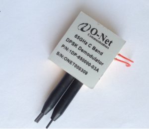
65GHz DPSK Demodulator, O-net 1DP-650000-03A, Delay Line Interferometer
Optical DPSK Demodulator, also known as Delay Line Interferometer (DLI), converts phase modulation to amplitude modulation over the entire C+L band in support of data transmission rates of 2.5, 10 or 40 Gb/s. The DPSK Demodulator is designed for phase modulated optical communication systems utilized in commercial, defense and space exploration markets. Th
e DPSK device plays a key role in improving signal quality and performance to meet the expanding demand for higher data rates and more complex transmission formats within current and next generation systems without major capital expenditure.
Features
Low insertion loss & PDL
Wide bandwidth
Low temperature-dependent frequency shift (TDFS)
Low polarization-dependent frequency shift (PDFS)
Central wavelength tunable
Applications
DPSK signal demodulation
Data rate optimization
Extend transmission distances
Electrical Specifications
| Parameter | Symbol | Min | Max | Unit | Note |
| Thermal tuning voltage | 0 | 5 | V | ||
| Thermal tuning power consumption | 1 | W | Typically 0.1W | ||
| RTD temperature range | -5 | 80 | °C | ||
| RTD characteristics | See Note |
Note : R(T)=Ro× (1+AT+BT2+CT3), where T is temperature in degree C, Ro=1000 ohm, A=3.9083×10⁻³,
B=−5.7753.9083×10-7, C=−4.183×10⁻¹² for T<0, C=0 for T>0.
Optical Specifications
| Parameter | Symbol | Min | Max | Unit | Note |
| Wavelength range (C-band) | 1527 | 1567 | nm | ||
| Free Spectral Range (FSR) | FSR | GHz | |||
| FSR error [1] | ΔFSR | 1 | % | ||
| Insertion loss (including connectors)[1] | IL | 2.2 | dB | typically 1.7 dB | |
| Insertion loss difference (between the two receiving ports) [1] | ΔIL | 0.7 | dB | ||
| Temperature dependent loss | TDL | 0.5 | dB | ||
| Extinction ratio [1] | 18 | dB | |||
| PMD [1] | 0.1 | ps | |||
| PDL [1] | 0.2 | dB | |||
| PDFS (polarization dependent frequency shift) [1] | PDFS | 1 | % | percentage of FSR | |
| TDFS (temperature dependent frequency shift)[2] | TDFS | ± 0.5 | GHz/°C | ||
| Optical path mismatch after interferometer (between the two receiving ports) [1] | 1 | ps | |||
| Return loss | RL | 40 | dB | ||
| Optical input power | Pin | 300 | mW | Per input port | |
| Thermal tuning range at 4.75[4] | TTR | 100 | GHz | 50-GHz FSR | |
| Net TTR (TTRmin[5] -70x | TDFS|) | 83 | GHz | 50-GHz FSR | ||
| Thermal tuning time constant [3] | 1 | Sec |
Note [1] Over wavelength range and all polarization states
Note [2] Frequency shift due to ambient temperature change
Note [3] Defined as the time required to reach half of the tuning range
Note [4] Unless otherwise stated, all specifications are EOL (20 years) and over the operating environments
