DESCRIPTION
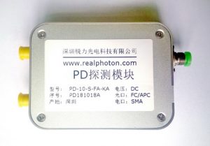
The PIN-TIA (Trans-Impedance Amplifier ) Photo-Diode Receiver Module consists of a key Oclaro’s InGaAs PIN photodiode and a low-noise mid-gain limiting preamplifier in a hermetic package. Differential outputs are provided to improve noise rejection for enhanced performance. It has been optimized for use in 10Gb/s metro or long-haul applications, using NRZ modulation, with or without FEC, at data rates up to 11.318Gb/s.
FEATURE
Sensitivity, -19.5dBm typical
Up to 11.318Gb/s with O and CL band
330mVpp differential output voltage
APPLICATION
Metro or Ultra Long-haul Optical Transmission
Large Capacity Data Center Interconnection
Testing and Measurement
SPECIFICATION
| Parameter | Unit | Min. | Typ. | Max. |
| Operating Wavelength** | nm | 1290 | 1550 | 1610 |
| 3dB Bandwidth(Small Signal) | GHz | 10 | 12 | – |
| 3dB Cut-off at Low Frequency | kHz | – | – | 52 |
| Sensitivity | dBm | – | -19.5 | – |
| Optical Overload | dBm | +1 | +3 | – |
| Output Voltage Swing(Single End) | mVpp | – | 160 | – |
| Maximum Data Rate | Gbps | – | 14 | – |
| Impedance Gain(Small Signal) | KΩ | – | 4.0 | – |
| PIN Responsivity | A/W | 0.7 | 0.9 | – |
| Dark Current | nA | – | – | 10 |
| Input Current for Onset of Limiting | uA | 40 | 50 | – |
| Input Power for Onset of Limiting | dBm | – | -12 | – |
| Signal Output and Couple | – | Differential, DC or AC Coupled | ||
| RF Output Port | – | K Type Female x2 | ||
| Optical Fiber and Connector | – | SM28-e, FC/APC | ||
| Adjustment Interface | – | Trimming Potentiometer, Manual | ||
| Operating Temperature | ℃ | 0 ~50 | ||
| Power supply* | – | DC 5~12V, 0.2A | ||
| Dimensions (L×W×H)* | mm | 80×60×20 |
Note: *The specifications subject to change without notice. * Class 2 ESD precautions must be observed when handling these devices. *The appearance and the key component vary according to different performance requirements.
ORDER INFORMATION
RX-PDR-1-2-3-4-5
| 1 | 2 | 3 | 4 | 5 |
| Package | Bandwidth | Wavelength | Electrical Interface | Connector |
| M=Module | 10=10GHz | C=C band | D=DC Coupled | FA=FC/APC |
| 20=20GHz | L=L band | A=AC Coupled |
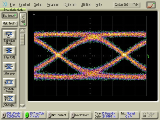
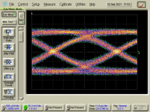
EYE DIAGRAM (NRZ at 11Gbps & 14Gbps)